

4.0 AM Detector
OBJECTIVES
GOALS
The objective of this lab is to understand how a diode detector circuit functions and build on the two-stage amplifier breadboarded in previous lab.
Chapter 4 Goals
-
Understand a simple diode detector circuit and analyze it with LTspice
-
Understand a biased diode detector circuit and analyze it with LTspice
-
Analyze a complementary feedback pair (CFP) detector with LTspice
-
Breadboard and test simple diode detector, biased diode detector, and CFP detector circuits
-
Add your chosen detector circuit to your radio's audio amplifier and test
4.1 Simple Diode Detector (LTspice)
A simple detector circuit consists of a diode rectifier circuit that includes an RC time constant that measures how long it takes the capacitor to discharge. Hence, the larger the RC product, the longer the discharge time. For this lab, the RC time constant will be fast enough to follow the audio signal, but slow enough to follow the carrier
First, a simple rectifier circuit is created in LTspice to simulate the capacitor's function. Using the schematic in Figure 1, a transient simulation of the circuit with a 5 V input amplitude is ran and the results are displayed in Figure 2. This rectifier circuit has a moderate time constant, but replacing the 1 kohm resistor with 10 kohm will increase the time constant and output the results shown in Figure 3. When comparing the two outputs, the rectifier with the 10 kohm resistor holds a charge better because the capacitor stays around the initial charge for longer.
Then, the schematic of the AM detector shown in Figure 4 is created to simulate an audio signal from an amplitude modulated signal. The three sine voltage sources connected in series correspond to the spectral peaks observed in the first lab. The amplitudes are set to 0.25 V, 0.75 V, and 0.25 V to achieve ~66% modulation. The output is displayed in Figure 5.
To ensure the more ideal AM detector is being breadboarded, the resistor values were changed out to determine which resistor will output the best results with the least distortion. Initially, the circuit began with a 1 kohm resistor before changing it to a 100 ohm resistor and re-running the simulation before getting the results shown in Figure 6. Although the output follows the input signal well, there is a lot of distortion at the peak of the charge. For this reason, 100 ohms is too small for this circuit. Thus, the resistor was changed to 10 kohm and the simulation was re-ran. The results shown in Figure 7 indicate that the capacitor is holding a charge well, however it does not follow the input well. Therefore, the 1 kohm resistor is the most ideal for this lab.
The signal voltages for the series-connected sources were also experimented on to observe how the output would change. The signal levels were decreased by dividing them all by 2; therefore, making the new amplitudes 0.125, 0.375, and 0.125. The results shown in Figure 8 suggest that the capacitor is not charging well because the peak is so small. So, this indicates that the lower signal amplitudes are too low for this detector.
4.2 Biased Diode Detector (LTspice)
A simple detector circuit is intended to extract an audio signal from the AM input as long as the signal is strong enough to turn on the diode. The issue occurs when the signal is too strong for the audio amplifier, causing the output to be distorted. To ensure that the diode will turn on and not distort the output, a biased diode detector will be used.
First, the biased diode detector is created in LTspice using the schematic shown in Figure 9. A transient simulation is ran and the results are displayed in Figure 10. For experimentation purposes, the input signal levels are again divided by 2 and re-simulated to get the results shown in Figure 11. When comparing the two results to the transient simulation in Figure 8, the biased diode results show a charge occurring whereas decreasing the signal amplitudes of the regular AM detector produced an almost miniscule charge.
Afterwards, the initial signal levels were divided by 10 to get 0.0125 V, 0.0325 V, and 0.0125 V as the new signal amplitudes. The transient simulation was re-ran and the results displayed in Figure 12 look more similar to the results shown in Figure 8 than Figure 11. This once again indicates that these new amplitude values are too small for the intended function of the circuit.
4.3 Complementary Feedback Pair Detector
A complementary feedback pair (CFP) detector is a clever configuration that can function as an AM detector. It is capable of extracting a very weak AM signal and outputting the ideal output that the AM detector needs.
The common-collector based detector, a configuration that can also be modified to function as an AM detector, shown in the schematic in Figure 13 features a strong input signal at 100 mV. After running the transient simulation, it outputs the results shown in Figure 14. When the signal levels are reduced to 1.5 mV, 5 mV, and 1.5 mV, the simulation is re-ran and produces the output shown in Figure 15. These results match the same non ideal output observed in Figures 8 and 12. To fix that, a CFP detector is constructed based on the schematic in Figure 16 in LTspice and the transient simulation outputs better results in Figure 17. The Rc1 resistor is included in this circuit to account for the additional current provided by the PNP transistor and create a more ideal output.
4.5 Constructing AM Detectors
First, the simple detector circuit was breadboarded similar to the circuit in Figure 4. An AM signal with a carrier frequency of 200 kHz and internal modulation of 1 kHz is fed through the circuit and the input and output are observed on the oscilloscope. The carrier amplitude began low at 100 mVpp and produced the output in Figure 18. For more ideal results, the input amplitude was increased to ~4 Vpp before the output shown in Figure 19 was achieved.
As previously analyzed using LTspice, different R1 resistors will generate varying outputs. To observe similar results, R1 is changed to 10 kohms to get the output in Figure 20 and 100 kohms to get the output in Figure 21. For the circuit with the 10 kohm resistor, the results are very similar to the simulation results from LTspice in Figure 7. As the resistor value is increased to 100 kohms, the peak of the output decreased as expected when R1 is too high.
Then, the biased diode detector shown in Figure 9 is constructed and fed an AM signal with the same specifications from the simple detector circuit. The results shown in Figure 22 are more ideal and follow the input signal better than the simple detector circuit.
Finally, the CFP detector is constructed using the schematic in Figure 16 and the same AM signal is fed through the circuit. The output was very close to ideal at low input amplitudes and worked best around ~500 mVpp to get the output shown in Figure 23.
Based on my results, the biased diode detector was chosen to add to the previously built amplifier and the schematic shown in Figure 24 guided the build.
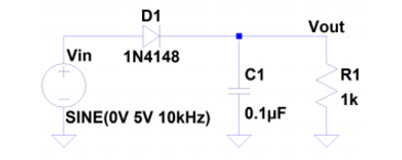
Figure 1: Simple Rectifier Circuit Schematic
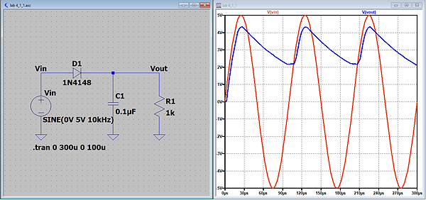
Figure 2: Transient of Rectifier w/ R1 = 1 kohm

Figure 3: Transient of Rectifier w/ R1 = 10 kohm

Figure 4: AM Detector Schematic

Figure 5: Transient of AM Detector
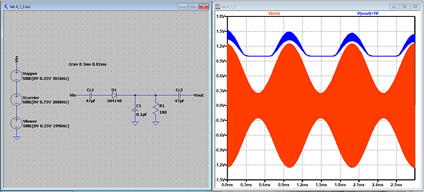
Figure 6: Transient of AM Detector w/ R1 = 100 ohm

Figure 7: Transient of AM Detector w/ R1 = 10 kohm

Figure 8: Transient of AM Detector w/ 1/2 Input Signal

Figure 10: Transient of Biased Diode

Figure 11: Transient of Biased Diode w/ 1/2 Input Signal

Figure 12: Transient of Biased Diode w/ 1/10 Input Signal

Figure 9: Biased Diode Detector Schematic
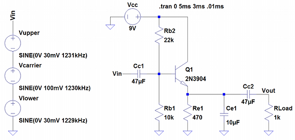
Figure 13: Common-Collector Based Detector Schematic
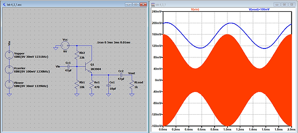
Figure 14: Transient of CC
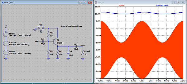
Figure 15: Transient of CC w/ 1/2 Input Signal
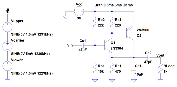
Figure 16: CFP Detector Schematic

Figure 17: Transient of CFP Detector

Figure 18: Simple Detector Output w/ Distortion

Figure 19: Simple Detector Output w/ 4 Vpp Input Amplitude

Figure 20: Simple Detector Output w/ R1 = 10 kohm

Figure 21: Simple Detector Output w/ R1 = 100 kohm

Figure 22: Biased Diode Detector Output

Figure 23: CFP Detector Output
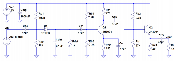
Figure 24: CE-CC Amplifier with Biased Diode Detector
Reflective Writing
For this lab, I realized how much troubleshooting goes into building radios. There were multiple instances where the equipment was malfunctioning and I initially thought that something was wrong with my circuit. After switching stations, I was able to get better results. However, I did have problems getting a sound out of my speaker when I tested my amplifier with the biased diode detector. I believe it had to do with not cutting down some of my resistors and losing power because of too many leads.