

6.0 Square Loop Antenna
OBJECTIVES
GOALS
The objective of this lab is to understand the purpose of an antenna for a radio and learn how to construct and tune a square loop antenna for the AM radio created using the previous labs.
Chapter 6 Goals
-
Design and construct a square loop antenna.
-
Tune antenna for optimum reception.

Figure 1: Joe Carr's Inductance Formula

Figure 2: Capacitance Formula

Figure 3: MATLAB Code solving Inductance & Capacitance
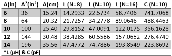
Table 1: Calculated Square Loop Inductance & Capacitance

Figure 4: Plot of Square Loop Inductance vs Loop Area

Figure 5: Square Loop Antenna around pizza box
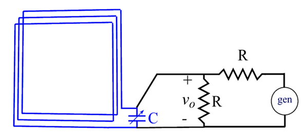
Figure 6: Antenna Testing Schematic

Figure 7: Power Level Received by Antenna

Figure 8: AM Channels picked up by Antenna

Table 2: Power Levels picked up by Antenna
6.1 Square Loop Antenna
A square loop antenna is a basic antenna architecture that will be used for the AM reception needed to pick up AM radio stations in Auburn. It has a primary coil defined by side length A, winding depth B, and number of turns N, where the loops are assumed to be evenly distributed over the winding depth. To tune, or adjust the resonance frequency, the antenna over the range for the Auburn area, the trimmer capacitor added to the primary windings is adjusted.
The antenna's inductance is given by Joe Carr's formula depicted in Figure 1, where A and B are in cm and inductance is in uH, and capacitance is calculated by rearranging the resonance frequency equation to get the formula in Figure 2. Its units are in pF.
6.1(a) - Preliminary Antenna Study
To calculate inductance and capacitance required for a given frequency and assumed square-loop parameters A, B, and N, the MATLAB code displayed in Figure 3 was used to quickly fill in Table 1 to observe the relationship between the inductance, area of the loop, and number of loops. To complete Table 1, the parameters were set to A = 14 inches, B = 2 inches, and f =1230 kHz, and the results were displayed in the graph in Figure 4.
6.1(b) Practical Square Loop Antenna Design
For the design, the Domino's Large pizza box, shown in Figure 5, was used to house the antenna and the dimensions were 14" x 14" x 1.875". To calculate the required inductance for the middle station (at 1400 kHz) using a 100 pF capacitor, the equation in Figure 2 was manipulated to get 129.236 uH. With that knowledge and the parameters of the pizza box, the number of exact turns is calculated by manipulating the equation in Figure 1 to be about 13 loops. The minimum capacitance needed to achieve this inductance (at 1520 kHz) is 84.83 pF and the maximum capacitance needed (at 1230 kHz) is 129.55 pF, meaning that the single 100 pF capacitor is sufficient for the design.
Then, the function generator is set up to send an AM frequency of 1230 kHz through the circuit displayed in Figure 6, where R is 50 ohms, to test the antenna. The output was observed using the spectrum analyzer function of the oscilloscope and configured to have a 1.23 MHz center frequency, 50 kHz span, -20 dBm reference amplitude level, and 200 Hz resolution bandwidth. With the results shown in Figure 7, the markers concluded that the power level received by the antenna is -52.7 dBm.
To maximize the spike at 1230 kHz, the antenna was tilted into an almost vertical position and held above the table and the power level was recorded into Table 2. A number of channels, indicated by the spikes in the spectrum in Figure 8, were picked up by the antenna and also recorded into Table 2.
Reflective Writing
This has been my favorite lab so far. Although creating the square loop antenna was tedious, the lab was fairly simple and yet gave me an output that worked correctly and was easy to understand. The static in the noise was most likely due to the lack of equal spacing between the loops, but there were a couple of radios that were able to pick up actual music behind all of the extra noise.